Sheet Metal Forming Features: Types, Applications & Design Guide
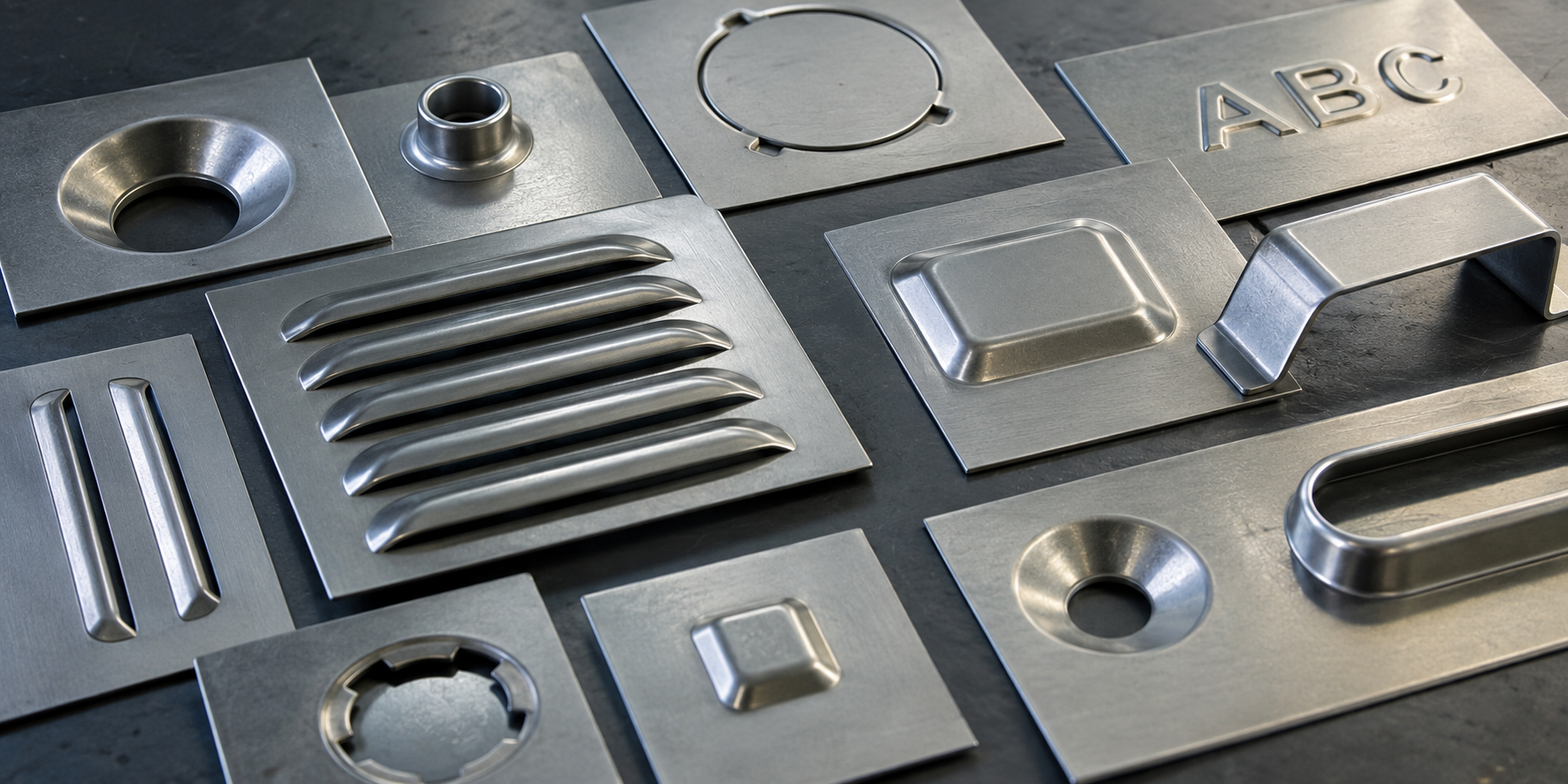
Learn how countersinks, embosses, louvers, beads, bridges, curls, and other sheet metal forming features improve strength, airflow, fastening, assembly, and functionality. Explore their applications and practical design considerations.
Sheet metal components are rarely just flat sheets with holes and bends. In many products, carefully designed local features improve fastening, stiffness, airflow, cable protection, alignment and assembly.
These features are commonly produced using forming tools on CNC turret punch presses, stamping presses or dedicated dies. Depending on the geometry, the material may be stretched, displaced, bent or partially sheared to create the required shape.
Understanding these features early in the design process helps engineers reduce part count, avoid unnecessary hardware, simplify assembly and improve manufacturability.
In this guide, we cover 11 commonly used sheet metal forming features, their applications and the design considerations that matter before releasing a part for manufacturing.
What is a sheet metal forming feature?
A sheet metal forming feature is a local geometric shape created by permanently deforming or partially cutting and deforming sheet metal.
Unlike a conventional punched hole, a formed feature changes the local profile of the sheet. Some features are created without removing material, while others combine shearing and forming.
Typical objectives include:
- Providing a flush or recessed seat for fasteners.
- Increasing local stiffness without adding material.
- Creating ventilation openings.
- Providing attachment points, guides and stops.
- Improving edge protection around holes.
- Adding identification marks or raised lettering.
- Supporting repeatable positioning during assembly.
Important: Not every feature can be produced using the same machine or tooling. The appropriate process depends on the geometry, material, thickness, production volume and required tolerances.
1. Countersink
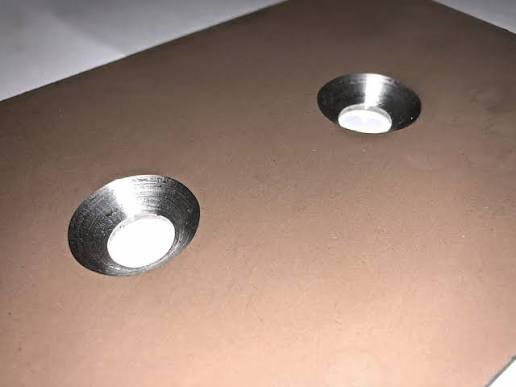
Primary purpose: Allow a countersunk screw or rivet head to sit flush with, or below, the surrounding sheet surface.
A countersink is a conical recess formed around a hole. It is commonly used where projecting screw heads could interfere with another component, create an uneven surface or obstruct sliding movement.
Typical applications
- Electrical enclosures and equipment covers.
- Machine guards and access panels.
- Sheet metal brackets and mounting plates.
- Flush-mounted panels and assemblies.
Design considerations
- Specify the fastener standard, nominal size and head geometry.
- Define the countersink major diameter and included angle.
- Check remaining material thickness beneath the recess.
- Verify the fastener sits correctly without excessive protrusion or an undersized bearing surface.
- Check for cracking, distortion and surface marking, particularly in thin or hard materials.
A countersink formed by a punch tool is not automatically equivalent to a countersink machined after drilling. The achievable geometry and surface finish depend on the forming process and tooling.
2. Burring for Thread Formation
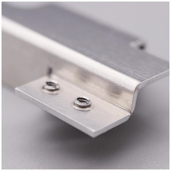
Primary purpose: Create an extended material wall around a hole to provide additional engagement length for a threaded connection.
Burring involves drawing or flaring the material around a pre-punched or simultaneously pierced hole to create a raised collar. The collar can subsequently be tapped, depending on the material, thickness, thread specification and process capability.
Compared with a thread cut directly into a thin sheet, a formed collar can provide more available thread engagement.
Typical applications
- Electrical control panels.
- Equipment housings.
- Sheet metal brackets.
- Mounting plates and light-duty threaded connections.
Design considerations
- Specify the finished thread size, pitch and required engagement.
- Confirm the recommended pre-hole diameter with the tooling or manufacturing supplier.
- Provide enough surrounding material for the collar to form without tearing.
- Check the collar height, root radius and proximity to adjacent features.
- Validate thread quality and pull-out performance for the intended load.
Do not assume a formed and tapped collar is suitable for every structural or fatigue-critical connection. Use a qualified fastening method where higher loads or repeated servicing are expected.
References: CONIC forming-tool guide · AMADA burring tooling
3. Curling
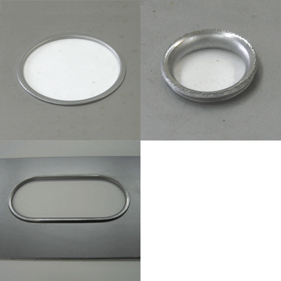
Primary purpose: Roll an edge or formed rim to create a rounded profile.
Curling bends the material around a radius, producing a rolled edge or lip. Depending on the geometry, it may be used to improve edge protection, guide cables or pipes, or create a more finished-looking component.
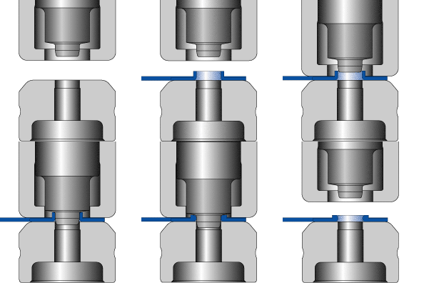
Some curling operations are performed after burring around a hole.
Typical applications
- Cable and pipe pass-throughs.
- Protective sheet metal edges.
- Enclosure openings.
- Rolled rims and formed lips.
Design considerations
- Define the required finished opening and outside diameter.
- Account for the material displaced during curling.
- Check tool access and clearance to adjacent walls.
- Avoid specifying a tight curl without validating the material's ductility and thickness.
- Consider whether the rolled edge must remain open, overlap or close completely.
For cable-routing applications, a formed edge should not automatically be treated as a qualified cable gland or abrasion-resistant grommet. Additional protection may still be required.
4. Embossing
Primary purpose: Create a raised or recessed shape in the sheet.
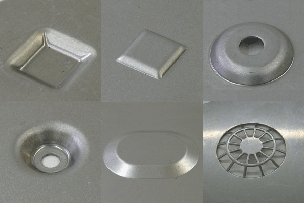
Embossing displaces the material to produce a local contour. Depending on the geometry, the feature may provide a seating surface, clearance, a decorative detail, a locating point or additional stiffness.
Embossing includes several related shapes, such as dimples, raised bosses, recessed seats and formed ribs.
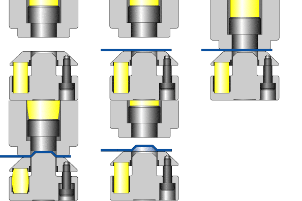
Typical applications
- Recessed bolt or nut seats.
- Mounting pads and locating features.
- Enclosure covers and appliance panels.
- Decorative surfaces and identification features.
- Local reinforcement around selected areas.
Design considerations
- Specify the feature height, width, depth and transition radii.
- Check the available clearance on both sides of the sheet.
- Evaluate thinning, stretching and cracking around the formed contour.
- Consider the effect on flatness and nearby holes.
- Confirm whether the feature is formed upward or downward relative to the primary datum.
A shallow dimple and a deep boss do not have the same forming requirements. Higher or more complex forms may need additional tooling development and process validation.
5. Knockout
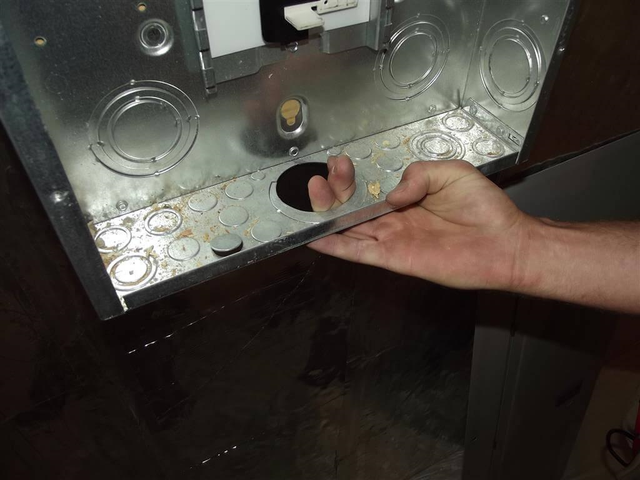
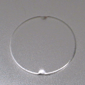
Primary purpose: Provide a removable section of sheet metal that can be opened when required.
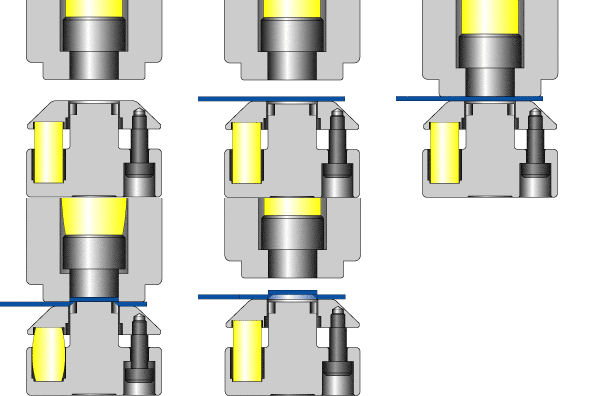
A knockout is typically created by partially shearing a defined outline while retaining small tabs that keep the slug attached to the surrounding sheet.
The retained section can later be removed to create an opening. The exact removal method depends on the knockout design and application.
Typical applications
- Electrical enclosure cable entries.
- Optional connector or conduit openings.
- Equipment panels with multiple configuration options.
- Service access and future connection points.
Design considerations
- Define the opening size and shape.
- Specify the intended knockout retention and removal method.
- Ensure the retained slug does not become a loose internal component.
- Check that removal will not damage the surrounding panel or its coating.
- Evaluate electrical safety, ingress protection and edge finishing where applicable.
For electrical enclosures, the knockout alone does not establish an IP rating or provide strain relief. Appropriate glands, fittings and sealing arrangements may be necessary.
6. Bridge and Double Bridge
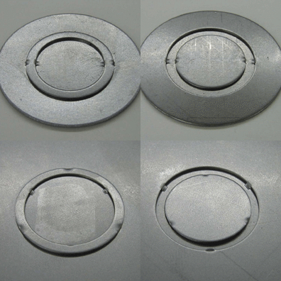
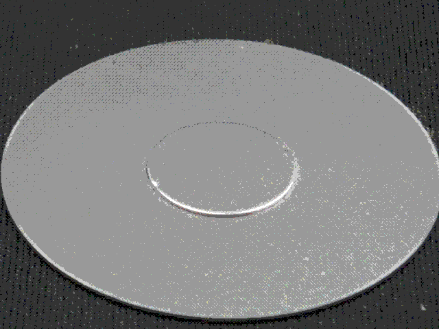
Primary purpose: Create a raised, supported section that can act as a guide, locator, retainer or clearance feature.
A bridge is formed by cutting and displacing part of the sheet to create a raised passage or supporting geometry. A double bridge uses a related arrangement with two formed sides or supports.
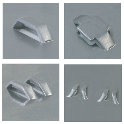
Typical applications
- Printed circuit board guides and retainers.
- Positioning features in equipment housings.
- Small component stops and supports.
- Sheet metal guides and partitions.
- Locating features in assembled products.
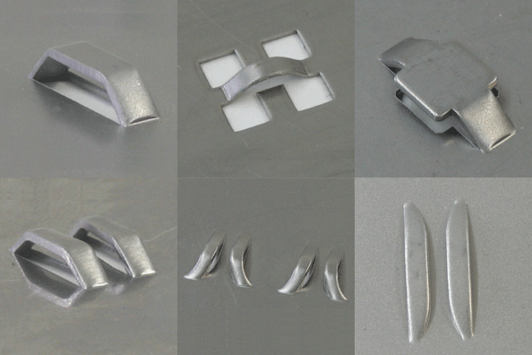
Design considerations
- Specify the bridge height, width, opening and formed length.
- Check clearance for the component being guided.
- Ensure the bridge does not obstruct assembly or service access.
- Consider edge quality and potential interference with cables or adjacent components.
- Validate the stiffness and retention force required by the application.
If the bridge is intended to retain a PCB or other electronic component, define the allowable clearance and contact locations rather than relying on the visual appearance of the feature alone.
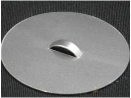
7. Lance for Airflow
Primary purpose: Create a cut-and-formed opening or tab that allows air to pass through the sheet.
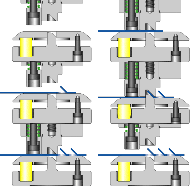
A lance operation combines partial cutting with forming. The resulting geometry can open a passage while leaving a portion of the material attached.
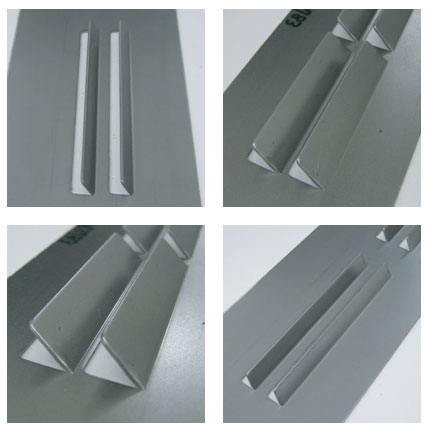
Airflow lances differ from fully enclosed openings because the cut-and-formed shape may include an attached flap or projecting section.
Typical applications
- Ventilated electrical enclosures.
- Electronic equipment housings.
- Equipment covers and cooling panels.
- Industrial cabinets with ventilation requirements.
Design considerations
- Define the opening length, width, pitch and formed height.
- Confirm the required free airflow area.
- Check the direction of the formed tab relative to internal components.
- Evaluate the risk of sharp edges, interference and local distortion.
- Validate airflow, pressure drop and thermal performance at assembly level when cooling is important.
A lance pattern does not guarantee a particular cooling capacity. The final result depends on the opening geometry, enclosure layout, fans, pressure losses and the operating environment.
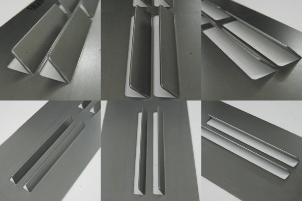
8. Louver for Airflow
Primary purpose: Direct air through a formed opening while providing a degree of shielding or directional control.
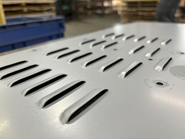
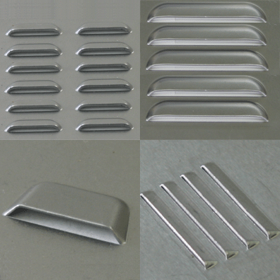
A louver is created by cutting and forming a section of the sheet into an inclined blade or raised opening. The geometry helps guide airflow and can reduce direct exposure to the interior.
Typical applications
- Electrical cabinets and control panels.
- Server and networking enclosures.
- Industrial machine covers.
- Ventilated equipment housings.
- Appliance panels.
Design considerations
- Define the louver length, width, pitch and angle.
- Check the free area available for airflow.
- Consider water, dust and debris exposure where relevant.
- Ensure the formed blades do not interfere with internal components.
- Check for cracking at the ends of the cuts and deformation between adjacent louvers.
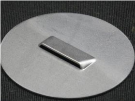 Louvers are not inherently waterproof or dustproof. If the enclosure needs a specified ingress-protection rating, validate the complete vent design and any additional filtration or sealing.
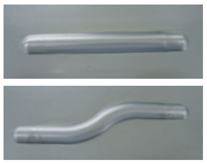
9. Beading
Primary purpose: Increase local stiffness by forming a bead or rib in the sheet.
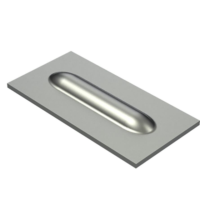
A bead is a continuous or segmented raised or recessed profile. It changes the section geometry and can improve resistance to bending or panel flex without adding a separate reinforcement part.
Typical applications
- Large enclosure panels.
- Machine covers and access doors.
- Electrical cabinet walls.
- Brackets and sheet metal supports.
- Panels that require reduced vibration or oil-canning.
Design considerations
- Specify the bead width, height, length and end geometry.
- Check the available clearance behind the panel.
- Maintain suitable transition radii to avoid local cracking.
- Consider the impact on flatness, mounting surfaces and adjacent bends.
- Assess the direction of the applied loads before choosing the bead orientation.
A bead can improve stiffness, but it does not automatically increase strength in every direction. Its effectiveness depends on the section geometry, material properties, boundary conditions and load direction.
10. Marking by Stamping
Primary purpose: Add identification marks by plastically deforming the sheet surface.
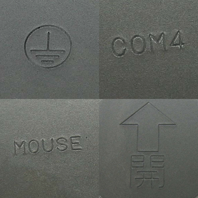
Stamp marking creates letters, numbers, symbols or other identification details using a punch or stamping tool. The mark may be recessed or raised depending on the tooling and process.
Typical applications
- Part numbers and revision identifiers.
- Serial numbers and traceability information.
- Assembly orientation indicators.
- Electrical symbols and grounding marks.
- Manufacturing and inspection references.
Design considerations
- Define the character size, depth, position and orientation.
- Ensure the marking remains legible after coating or finishing.
- Avoid placing marks on critical sealing surfaces or tight-tolerance interfaces.
- Check whether marking could cause unacceptable distortion on thin panels.
- Consider whether the design needs permanent identification or only a cosmetic label.
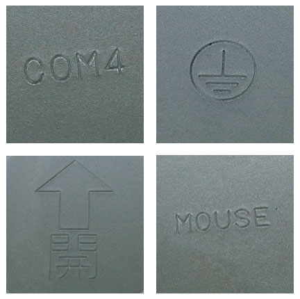
For traceability-critical products, validate readability after the complete finishing process rather than inspecting the mark only on the uncoated sheet.
11. Marking by Embossing
Primary purpose: Create raised or recessed letters, numbers, symbols or logos.
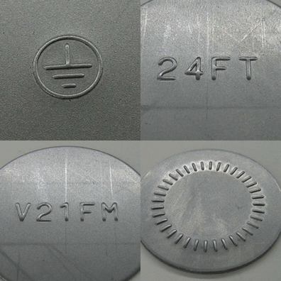
Emboss marking uses shaped tooling to produce a three-dimensional mark. Compared with a shallow stamped impression, the resulting letters or symbols may be more prominent and tactile.
Typical applications
- Brand names and product identification.
- Control panel labels and symbols.
- Electrical and safety markings.
- Decorative product details.
- Identification on sheet metal housings.
Design considerations
- Specify the text or symbol, height, width and formed depth.
- Check the minimum character size for the selected material and tooling.
- Consider the effect on the reverse surface.
- Keep embossed markings clear of mounting interfaces and sealing areas.
- Validate appearance after painting, powder coating or other surface treatments.
Embossed markings are useful where a durable physical identifier is required, but very small text and intricate logos may not reproduce reliably in every material or thickness.
References: CONIC forming-tool gallery · AMADA special-order tooling
Quick Comparison: Which Form Should You Use?
| Feature | Main function | Example application |
|---|---|---|
| Countersink | Flush fastener seating | Machine covers |
| Burring | Extend the material around a hole | Threaded enclosure holes |
| Curling | Create a rolled edge or rim | Cable pass-throughs |
| Embossing | Form a raised or recessed shape | Mounting seats |
| Knockout | Provide a removable opening | Electrical cabinets |
| Bridge | Create a raised guide or retainer | PCB positioning |
| Airflow lance | Create a cut-and-formed air passage | Equipment panels |
| Louver | Direct air through a formed opening | Ventilated enclosures |
| Beading | Improve local panel stiffness | Large covers |
| Stamped marking | Add identification marks | Part traceability |
| Embossed marking | Create raised or recessed symbols | Product branding |
Design for Manufacturability: What Engineers Should Check
The success of a formed feature depends on more than its nominal dimensions. The material, tooling, feature location and sequence of operations all influence the final result.
1. Material and thickness
Confirm the sheet material, thickness, temper and ductility. Stainless steel, aluminium and mild steel may respond differently to the same forming geometry.
2. Feature height and transition radii
Deep forms, tight radii and narrow features can increase local strain and the risk of cracking. Validate the geometry with the manufacturing supplier rather than relying on a universal height-to-thickness rule.
3. Clearance to adjacent features
Formed features need sufficient room for the material to move and for the tooling to engage. Closely spaced holes, bends and forms can interfere with each other or distort the surrounding sheet.
4. Form direction
Specify whether the feature is formed upward or downward relative to the drawing datum. The direction can affect assembly clearance, tooling access and the usable surface of the part.
5. Tolerances and inspection
Identify which dimensions are functionally critical. For example, a louver's cosmetic profile may tolerate variation that would be unacceptable for a locating bridge or threaded collar.
6. Tooling and production volume
Standard turret punch forming tools may be suitable for repeatable, relatively simple features. Complex geometries or high production volumes may justify dedicated tooling or another manufacturing process.
7. Secondary operations and finishing
Consider tapping, deburring, coating, painting and assembly in the process plan. Forming can introduce local marks, burrs or distortion that affect later operations.
Final Takeaway
Sheet metal forming features help engineers integrate functionality directly into a component. A countersink provides a flush fastener seat, burring supports threaded connections, louvers and airflow lances create ventilation paths, beads improve panel stiffness, and bridges provide useful guides or retainers.
The best feature is not necessarily the most complex one. It is the feature that satisfies the functional requirement while remaining practical to manufacture, inspect and assemble.
Before finalising a CAD model, discuss critical dimensions, material thickness, forming direction and tooling constraints with your manufacturing partner.
Frequently Asked Questions
What are the most common sheet metal forming features?
Common features include countersinks, burring, curling, embossing, knockouts, bridges, louvers, airflow lances, beading and stamped or embossed markings.
What is the difference between embossing and beading?
Embossing creates a raised or recessed shape that may serve a functional, locating or decorative purpose. Beading creates a rib-like profile primarily to improve local stiffness.
Can sheet metal forming features be produced by a CNC turret punch press?
Many common features can be made using compatible turret punch forming tools. Feasibility depends on the machine, available tooling, material, thickness, feature geometry and production requirements.
What is the purpose of burring in sheet metal?
Burring forms an extended collar around a hole. The collar can provide additional material for tapping or improve the geometry of a formed opening.
Do louvers make an enclosure waterproof?
No. Louvers support ventilation but do not inherently provide a specified water or dust ingress rating. The complete enclosure design must be evaluated for the required protection.
What should be specified on a sheet metal forming drawing?
Specify the feature geometry, critical dimensions, material and thickness, form direction, applicable tolerances and any functional requirements such as thread engagement, airflow or fit.
Ready to manufacture your sheet metal design?
Design for manufacturability from the start. Explore your custom sheet metal part requirements with TensorCut and reduce avoidable iterations between design and production.